

Common Faults and Maintenance of Yaskawa Inverters
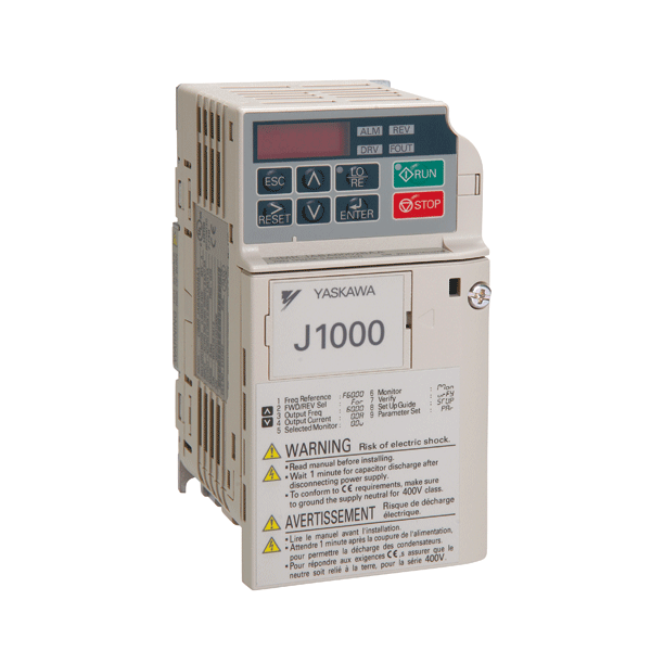
Common Faults and Maintenance of Yaskawa Inverters
In the use of Yaskawa inverters, we still encounter various faults. The following is a discussion of common faults of Yaskawa inverters for the benefit of a wide range of users.
Common Faults of Yaskawa Inverters
(1) Switching Power Supply Damage Switching power supply damage is the most common fault in many inverters, usually caused by a short circuit in the load of the switching power supply. In the design of the switching power supply circuit of many inverters, Yaskawa inverters should be said to be relatively successful. The 616G 3 adopts a two-stage switching power supply, which is somewhat similar to the Fuji G5. The first-stage switching power supply first converts the DC voltage of more than 500 volts on the DC bus side into a DC voltage of more than 300 volts. Then, through the secondary winding of the high-frequency pulse transformer, lower voltages such as 5V, 12V, and 24V are output to supply the control board, drive circuit, detection circuit, etc., of the inverter for use. In the design of the second-stage switching power supply, Yaskawa inverters use a controllable voltage regulator called TL431 to adjust the duty cycle of the switching tube, thereby achieving the purpose of stabilizing the output voltage. The LG inverter we talked about in the previous few issues also used a similar control method. The QM5HL-24 used as the switching tube and TL431 are relatively easy to damage components. In addition, if we hear a piercing scream during use, this is caused by the pulse transformer, and there may be a short circuit on the output side of the switching power supply. We can find the fault from the output side. In addition, when there are no displays, no voltage at the control terminal, DC12V, 24V fan does not rotate, etc., we should first consider whether the switching power supply is damaged.
(2) SC Fault The SC fault is a relatively common fault of Yaskawa inverters. IGBT module damage is one of the reasons for the SC fault alarm. In addition, damage to the drive circuit can also easily lead to an SC fault alarm. In the design of the drive circuit, Yaskawa uses the drive optocoupler PC923 on the upper bridge, which is a type of optocoupler with an amplifier circuit specifically for driving the IGBT module. Yaskawa's lower bridge drive circuit uses the optocoupler PC929, which is an optocoupler with an internal amplifier circuit and detection circuit. In addition, phenomena such as motor jitter, unbalanced three-phase current and voltage, and frequency display but no voltage output may also indicate IGBT module damage. There are many reasons for IGBT module damage. First, the external load fails, which leads to the damage of the IGBT module, such as a short circuit or jam of the load. Second, aging of the drive circuit may also cause the drive waveform to be distorted or the drive voltage to fluctuate too much, leading to damage of the IGBT and causing an SC fault alarm.
(3) OH - Overheat Overheat is a fault that is often encountered. When encountering this situation, the first thing to consider is whether the cooling fan is running. By observing the outside of the machine, you can see if the fan is running. In addition, for machines above 30kW, there is also a cooling fan inside the machine. The damage of this fan will also cause an OH alarm.
(4) UV - Undervoltage Fault When an undervoltage fault occurs, the input power supply should be checked first to see if there is a phase loss. If there is no problem with the input power supply, we should check if there is a problem with the rectifier circuit. If there is no problem, we should check if there is a problem with the DC detection circuit. For 200V machines, when the DC bus voltage is below 190VDC, the UV alarm will appear; for 400V machines, when the DC voltage is below 380VDC, the fault alarm will appear. The main thing to check is whether the step-down resistor is open.
(5) GF - Ground Fault Ground fault is also a commonly encountered fault. In addition to ruling out the problem of motor grounding, the most likely part to fail is the Hall sensor. Due to the influence of temperature, humidity, and other environmental factors, the working point of the Hall sensor is easy to drift, causing a GF alarm.